
Getting Started with Ecolink TBZ500 Z-Wave Thermostat

Overview
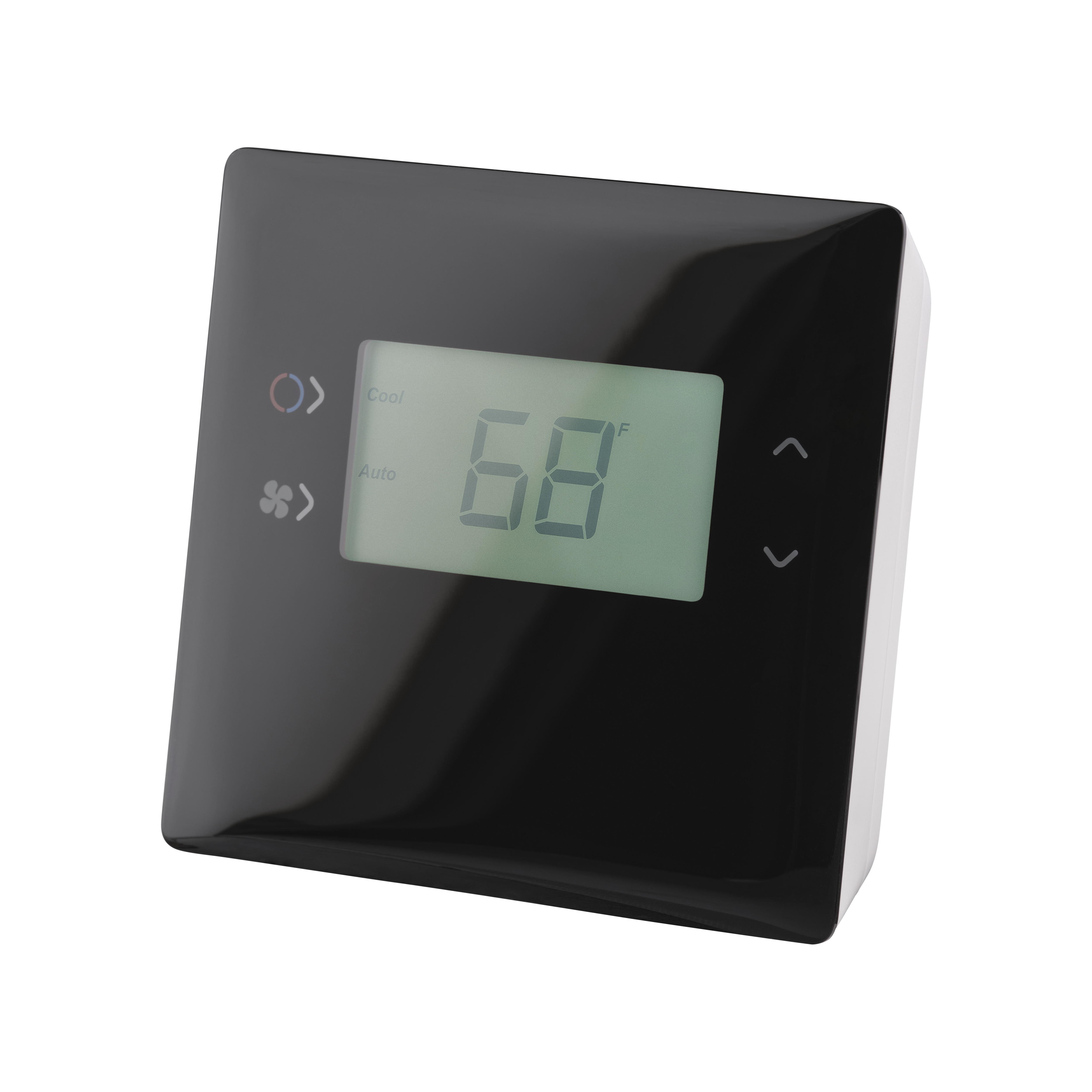
The TBZ500 is a Z-Wave® wireless digital thermostat that supports both 24VAC and battery operation. Designed to control the majority of HVAC systems including standard gas/electric type and heat pump system, the TBZ500 contains a robust thermostat interface and is designed for use with communicating systems where remote monitoring and/or remote control are desired.
DIY Home Automation & Pro Security
Replacing your current thermostat with the TBZ500 Z-Wave thermostat paired with a security system provides greater control of your energy and can remotely control, automate and monitor the home’s temperature.
The TBZ500 thermostat can replace your current thermostat and is compatible with major security systems/panels.
Features
- Z-Wave Plus® Certified, S2 Security
- FW update via Z-Wave® OTA
- Standard gas/electric HVAC Systems: 2-stage heating, 2-stage cooling
- Heat Pump HVAC Systems: 3-stage heating, 2-stage cooling
- Fan system: Selectable for gas or electric heat systems
- Heat Pump Change Over Valve (reversing valve): Selectable for change over with heat or change over with cool (O or B output)
- Emergency Heat: In Heat Pump Mode, Emergency Heat Mode is selectable from the thermostat
- Compressor short cycle protection delay of 5 minutes (adjustable)
- Backlit fixed 128 segment B/W LCD with 7-character message bar

Compatible with:

Setup Instructions
- Installation Preparation
- Conventional System Wiring
- Heat Pump Wiring
- Finish Wiring
- System Setup - Conventional/Fan Type
- System Setup - Heat Pump
- Enroll on Z-Wave Network
Follow the steps below to remove your existing thermostat and prepare for thermostats installation by identifying all wires via the procedure below:
Step 1: Turn off power to the HVAC system. Usually at the HVAC system or the circuit breaker panel.
Step 2: Remove cover of old thermostat to expose the wiring terminals.
Step 3: Take a picture of the wiring terminals! This will help with troubleshooting later if needed.
Step 4: Mark the wires attached to the terminals with the wiring labels included.
Step 5: Use the terminal labels and not the wiring color to mark the wires.
Step 6: Remove the old thermostat base.
Step 7: Mount the thermostat base to the wall using the wall anchors and screws provided. Level as needed.
Step 8: Proceed to the installation steps for your system type.
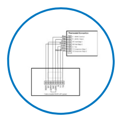
Connect the wires according to the HVAC system type as shown.
Step 1: R vs RC and RH Connections: Single Transformer HVAC Systems. Typical modern central HVAC installations have an integrated heating and cooling system with a single 24VAC transformer. For these systems, there is only on 24VAC “R” wire and it can connect to either RC or RH terminal on the thermostat. The thermostat is supplied with an RC-RH jumper installed. Do not remove the jumper for common transformer HVAC systems.
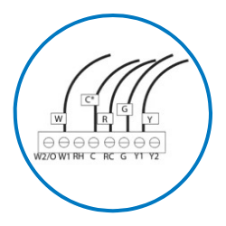
Step 2: If you have additional wires for 2 stage systems (W2, Y2), Continue wiring as shown. Otherwise, proceed to Finish Wiring.
Connect the wires according to the HVAC system type as shown.
Step 1: R vs RC and RH Connections: Single Transformer HVAC Systems. Typical modern central HVAC installations have a integrated heating and cooling system with a single 24VAC transformer. For these systems, there is only one 24VAC “R” wire and it can connect to either the RC or RH terminal on the thermostat. The thermostat is supplied with an RC-RH jumper installed. Do not remove the jumper for common transformer HVAC systems.

Step 2: If you have additional wires for 2 stage systems (W2, Y2), Continue wiring as shown. Otherwise, proceed to Finish Wiring.
Complete the wiring process by following the instructions below.
Step 1: Check that the wires are screwed into the terminal blocks firmly.
Step 2: Gently pull on the wires to confirm the connection.
Step 3: Push all the excess wiring back into the wall.
Step 4: Mount the thermostat.
=> 24VAC Powered ? If the thermostat is 24VAC powered (24VAC common “C” wire is connected), DO NOT INSTALL BATTERIES!
=> Battery Powered Thermostat: If the thermostat is battery powered (NO 24VAC common “C” wire connected), install 4 NEW Alkaline AA batteries into the back of the thermostat.
Step 5: Proceed to Powering the Thermostat.
Step 6: Install the thermostat on to the base.
Step 7: Turn on power to the HVAC system/thermostat.
Step 8: Proceed to the configuration step for your system type.
Configure the Fan type for your conventional system:
- Gas? Your fan is controlled by the furnace. Congratulations! Your setup is already completed!
- Electric? Turn your fan on with heat cal and follow the steps below:
Step 1: Go to the Menu screen by pressing and holding the FAN button for 5 seconds Press the down arrow to select the SYSTEM menu and press Select. Set the following: SYSTEM TYPE: Set to STANDARD FAN TYPE: Set to ELECTRIC for electric heat (fan on with heat call).
Step 2: If you have additional wires for 2 stage systems (W2, Y2), proceed to 2nd Stage System Setup; otherwise enroll the thermostat in your network.
Step 3: If you have additional wires for 2 stage systems (W2, Y2); otherwise enroll the thermostat in your network.
Step 4: Selected to configure 2nd heat/cool stage
For Two Stage Heat/Cool Systems: Go to ADVANCED SYSTEMS SETTINGS menu.
From the Setup menu screen, press and hold the Fan and Down arrow buttons for 5 seconds. Use the Down arrow button to select the following: 2ND STAGE HEAT ENABLE: Enable second stage heating output If a single stage heating system, leave this set to N
If a 2 stage heating system, set to Y to enable. 2ND STAGE COOL ENABLE: Enable second stage cooling output If a single stage cooling system, leave this set to N. If a two stage cooling system, set to Y to enable.
Configure as Heat Pump System:
Step 1: Go to the Menu screen by pressing and holding the FAN button for 5 seconds
Press the down arrow to select the SYSTEM menu and press Select.
Set the following:
SYSTEM TYPE: Set to HEAT PUMP
CHANGE OVER: For changeover with cooling systems (Orange wire): set to WITH COOL (most common and default setting)
For changeover with heating systems (Brown wire): set to WITH HEAT
Step 2: You must configure the thermostat’s changeover valve setting to work correctly with your HVAC system. Check your system information to be sure and note the color of original thermostat wire and the terminal it was connected to. No matter what the old stat connection was (O or B), connect the wire to the thermostats W2/O terminal.
Step 3: If you have additional wires for 2 stage systems (W2, Y2), proceed to 2nd Stage System Setup; otherwise enroll the thermostat in your network. Selected to configure 2nd heat/cool stage.
Step 4: For Two Stage Heat/Cool Systems:
Go to ADVANCED SYSTEMS SETTINGS menu.
From the Setup menu screen, press and hold the Fan and Down arrow buttons for 5 seconds. Use the Down arrow button to select the following:
2ND STAGE HEAT ENABLE: Enable second stage heating output If a single stage heating system, leave this set to N.
If a 2 stage heating system, set to Y to enable.
2ND STAGE COOL ENABLE: Enable second stage cooling output. If a single stage cooling system, leave this set to N. If a two stage cooling system, set to Y to enable.
Follow the following steps to add the thermostat to a Z-Wave network.
Step 1: Follow the instructions provided with your system for enrolling the thermostat.
Step 2: Press and hold the FAN button on the Thermostat until the screen changes to the Menu screen.
Step 3: Press the UP button until ZWAVE is shown in the Status Display line then press SELECT.
Step 4: INSTALL should be shown on the status line.
Step 5: When instructed by your system installation to add the thermostat to the network press the SELECT button to install. Wait until SUCCESS or FAILED is shown on the status display.
Step 6: Press DONE on the Thermostat to exit the ZWAVE screen.
Step 7: Press DONE on the Thermostat again to exit the Menu screen.
Step 8: Once enrolled on your system’s network, continue to follow the instructions provided to complete the enrollment and naming of the thermostat.
Step 9: The indicator should be shown on the Thermostat Main screen indicating the thermostat has successfully been enrolled into the Z-Wave network.
Installation Video

Specifications
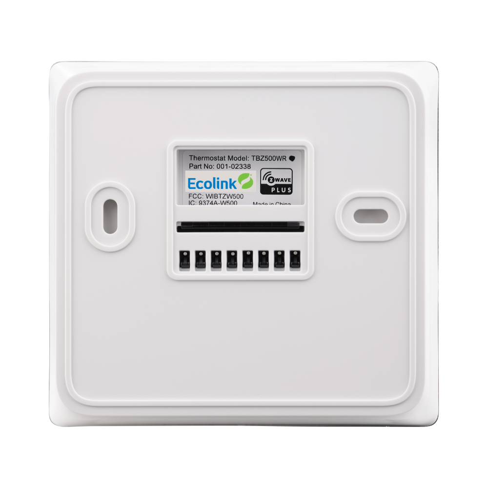
TBZ500W
TBZ500B
Flexible Power
Battery
- 24-month battery life with four (4) AA Alkaline batteries
- Low Battery Indication
Powered
- Hardwired 24VAC
Note: 24V operation requires both 24VAC (R) and 24VAC common (C) wires from the HVAC System
Fan Control
- Fan can be configured on and auto (controlled by HVAC)
Wiring Requirements
- Uses standard thermostat connections (C, RC, RH, W1, W2/0,Y1,Y2,G) – 18 AWG
Compliance
- USA: FCC Compliant to CFR47, Part 15B
- Canada: Industry Canada RSS 210, Issue 8